kicker mount design parameters

sly_karma

Crew Member
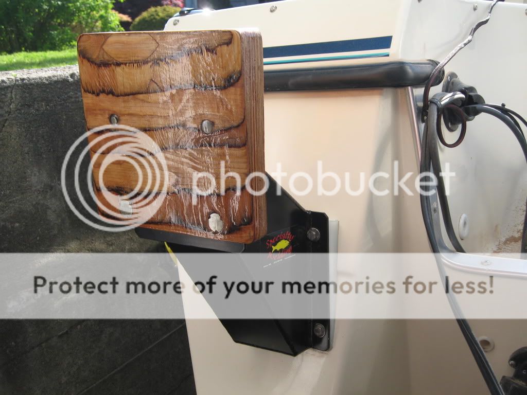
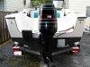
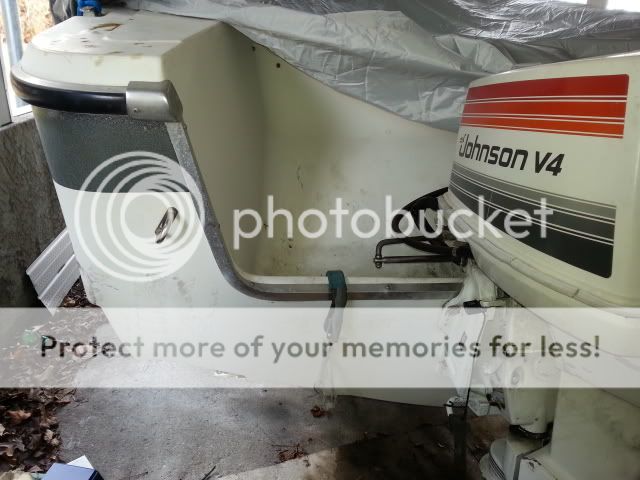
I have an old fibreglass Lund 19.5 hull with a transom design that is making it difficult to mount a kicker. You can see from the picture that the transom's engine cutout is very wide and there is not enough room for the kicker to mount next to the main (to give some idea of scale, the rail space to the left of the main's steering linkage is just 9"). There is also little room on the full height portion of the transom, and through-bolting in this area woukld be very difficult as there is a foam floatation cell moulded into the hull in that area.

All the advice I've received to date is to have a custom mount plate made that will mount the kicker in a position roughly centred on the vertical transition from the engine cutout to the full gunwale height. The mount to the transom will be a hybrid - half of it hooked onto the engine mount rail, and part of it through bolted off to port side from where the mount rail ends. I have a welder friend that can make me a stainless or aluminum bracket, but I need some info on clearances and standoff before we design it.

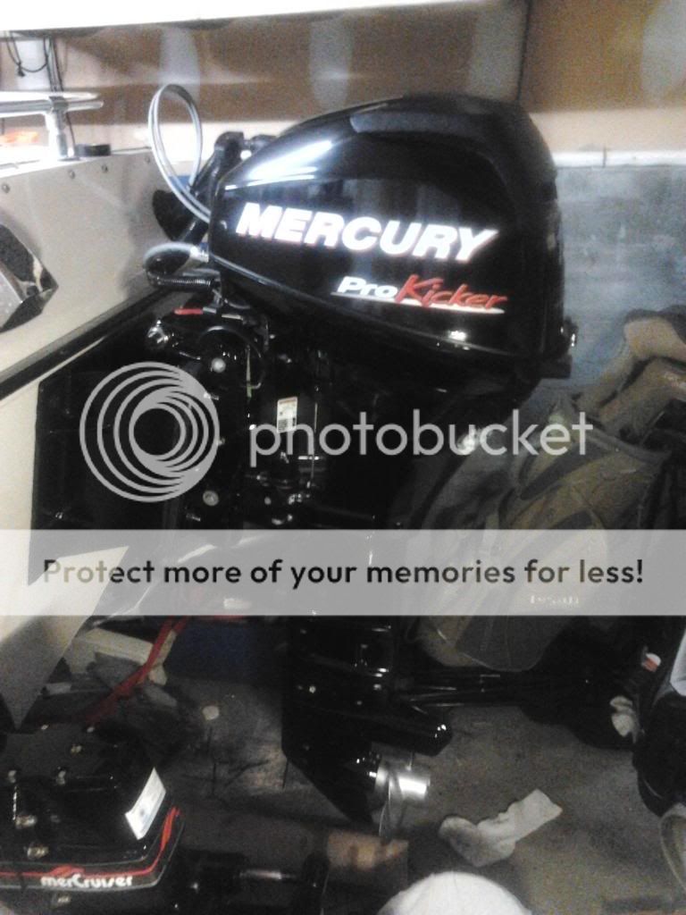
The engine is a Merc 9.9 stroke electric start/remote control, weight 200 lb. It has a 20" shaft, same as the main.

What I'd like to know is:
  • How far does the mount need to stand off the transom to allow for engine tilt?
  • How much offset to port?
  • Do I set the mount at the same height as the main?
  • Any other design advice re construction, materials, etc?


20130217_125858_zpseb8a7e55.jpg


Thanks in advance for all advice.

Sly
 
How far does the mount need to stand off the transom to allow for engine tilt? STAND-OFF IS A FUNCTION OF NOT ONLY TRANSOM CONFIGURATION BUT ALSO KICKER DESIGN --- FOR INSTANCE, A REMOTE STEER KICKER (LIKE YOURS) WOULD REQUIRE LESS STAND-OFF THEN A TILLER STEERED KICKER WHEN TILTED. DEPENDING ON THE DEPTH OF YOUR SPLASH WELL (AS MEASURED FROM THE TRANSOM TOWARDS THE BOW OF THE BOAT) THERE MIGHT BE LOTS OF ROOM FOR A TILTED REMOTE CONTROLLED KICKER WITH MINIMAL TRANSOM STAND OFF.

I WOULD WORRY MORE ABOUT CLEARANCE BETWEEN THE KICKER AND THE MAIN ENGINE, THOUGH. VISUALLY, (FROM YOUR PICTURE) IT LOOKS LIKE IF THE KICKER IS CENTERED BETWEEN THE PORT EDGE OF THE SPLASH WELL AND THE MAIN ENGINE, A HARD-STARBOARD OR HARD-PORT TURN MIGHT HAVE YOUR MAIN ENGINE COWLING GETTING UP REAL CLOSE AND PERSONAL TO THE COWLING OF YOUR KICKER--- HAVE YOU MEASURED THE MERC'S COWLING TO SEE IF THERE WILL BE ENOUGH CLEARANCE IN THAT TIGHT SPOT ONCE THE MAIN IS THROWN OVER HARD TO STARBOARD OR HARD TO PORT????

How much offset to port?--NOT SURE WHAT YOU MEAN BY THIS---I THOUGHT YOU WERE GOING TO CENTER THE KICKER ??? WHAT'S BEING OFFSET TO PORT?

Do I set the mount at the same height as the main? IT'S GOING TO COME DOWN TO CLEARANCE BETWEEN THE TWO COWLINGS. YOU MIGHT BE FORCED TO RAISE THE KICKER SO IT SITS A BIT ABOVE THE MAIN ENGINE---IT APPEARS FROM YOUR PIC THAT THERE WILL BE MORE CLEARANCE IF THE KICKER SITS HIGHER ON YOUR PLATE (ASSUMING THE CAVITATION PLATE WILL STILL BE UNDER WATER WITH THAT EXTRA RISE)

Any other design advice re construction, materials, etc? THOSE 9.9 MERCS ARE ALOT OF REAL ESTATE ON A KICKER TRANSOM. I'D GO WITH POWDER-COATED WELDED ALUMINUM AND I'D ENSURE THAT THE THROUGH-BOLTING IS DONE PROPERLY WITH MULTIPLE SECURE POINTS

Speaking of through-bolting.....

Are you sure you can't through-bolt on the full-height portion of your transom? If you have access to the foam you can dig it out until you get to the glass. You could then fab a stainless backing plate and tack your fixed bracket right about where that stainless eye bolt sits---that where it really should go.

Even with that minimal surface area, you could get a bracket built that would be burly enough for your Merc but would fit right where that stainless eye-bolt sits. Much better placement, and you wouldn't run the risk of having those two engines interfering with each other. That space in your splashwell just looks too tight, (at least from the picture)

Here's a bracket I had fabbed out. My kicker sits higher then the main engine (had to go for a X-long shaft) ----I had to go that route because once tilted, the kicker wouldn't have cleared the top of the gunnel

I fabbed out the marine-ply transom add-on so I could lift or lower as necessary to get the proper clearance for the kicker (tiller controlled which needed more clearance)

IMG_3230.jpg


IMG_3229.jpg


IMG_3301.jpg
 
Last edited by a moderator:
This is what I did on my former boat. I used a few pieces of starboard between the transom and the mounting pad to give me enough clearance for the the kicker. I used a tie bar between the main and kicker for steering. I had a Yamaha 8 HT on that bracket. With that set up, whenever I lifted the kicker I had to lean it towards the port side so it would not interfere with the main engine, other than that it worked well.

You can fab up a bracket out of lumber and then clamp it on the transom and hang the kicker on it to check everything out. By the way I would be surprised if you kicker weighs 200 lbs, probably more like 120 lbs. Good luck.
 

Attachments

  • 100_0119.jpg
    100_0119.jpg
    90.3 KB · Views: 548
I guess you have an awesome kind of boats. And there are lot of more boats and model will get. once your google it out.
 
What I did on my last 17 Double Eagle was to take the mounting pad from a lift type bracket. It was a black composite one. Use the 4 mounting holes to bolt it directly to the transom, centered between the main and the full part of the transom. The top of the pad when mounted is about 4 to 6 inches higher than the existing cut out transom....so your kicker will be that much higher than your main. This gets it over the top of the steering linkage and gives you more clearance. The motor will also tilt up into the well just like your main. Three things to make it work...a long leg on the kicker, a remote control model kicker so you don't have a tiller handle and a tie bar to steer both engines from your helm. If you use a tiller handle model it will have a clearance problem with the side of the well on the port side.
 
Thanks to the two non-bot members who replied! Here's a picture that hopefully clarifies my intentions:

bth_20130217_125858_zpseb8a7e55.jpg


The kicker can't mount on the regular rail because there's only 9" of space available when the main's steering is turned to full port position. I think the best position is another 3-4" to port which I've indicated with a red centre line. That brings problems of its own because now the kicker needs to be stood off the transom so it can tilt when not in use, hence my original question: how much standoff?

I'm a carpenter so I did indeed consider building a prototype in wood, but how to mount it temporarily to check kicker clearance without drilling the hull? (Note to self: need to explore that further, a combination of clamps and jigs and sawhorses can probably be made to work).

Looking from inside the hull I can see that the floation cells don't extend down below the level of the engine mount rail, so the solution should involve a plate that mounts down low where there is access - something like what Sharphooks posted. The float cells are really large - they run forward for the entire depth of the splashwell and they're reinforced with a fibreglass shell, so working in their vicinity is difficult and to be avoided if possible. I guess I can get away with lifting the kicker up some since the hull deadrise means the prop will be in clear water even as we come up close to the cav plate touching the surface. Clearly this is a problem in all three dimensions!

Keep those calls and postcards coming in folks.
 
A friend of mine had a similar problem to you setup. His solution was to mount the kicker on the port side transom but shimmed the kicker 2 or so inches up. That way the mains steering arm had clearance. He also modified the kicker by cutting off some material where he had interference with the transom. He has his kicker and his main tied together, with a tie bar on the front, all the time. He fabricated some creative brackets to join the tie bar. The kicker, when in the up position, follows the main when being turned and has no clearance problem on his boat. Now he is using an 8hp merc 2 stroke so yours maybe wider then his and may not be work the same.
GLG
 
Becoming clear that I really need to come up with a way of experimenting with different kicker locations before I design any bracket.
 
Thanks to the two non-bot members who replied! Here's a picture that hopefully clarifies my intentions:

View attachment 6160


The kicker can't mount on the regular rail because there's only 9" of space available when the main's steering is turned to full port position. I think the best position is another 3-4" to port which I've indicated with a red centre line. That brings problems of its own because now the kicker needs to be stood off the transom so it can tilt when not in use, hence my original question: how much standoff?


Keep those calls and postcards coming in folks.
I needed minimum 8.5" for my merc 15hp.
Measure 20 times cut once. I built the aluminum bracket for 8" of standoff then added 1/2" plywood moving the motor out until it was close and but not touching. Add more plywood if its too close.

2012-07-02211218_zps789e4e0c.jpg
 
Last edited by a moderator:
Hey Sly

Now I see what you meant about "offset to port"

I think you're on the right track---at first I thought that kicker was going to be centered in that 9" of transom between the main engine and the edge of the splash well. That would have been a tough clearance nut to crack.

So you have three things to think about--- offset from the stern of the boat, height to make sure your Merc clears the top edge of the gunnel when fully tilted, and, enough clearance so the Merc turns freely on the shaft axis when she's in operating position

If you want, I can measure the offset on mine and the height relative to the top of the gunnel. My Honda is tiller controlled---Honda has a huge tiller arm and for electric tilt, the tilt control box requires HUGE clearance once sitting on the bracket---you can see how much aluminum flange bracket "reveal" there is peeking out from under the marine ply---I had to keep experimenting with the plywood part of the bracket, lifting it until I finally got enough clearance for the Honda before finally committing to the bolt holes of the plywood riser.

Anyway, I can provide bracket measurements if that will help.
 
Last edited by a moderator:
Thanks Sharphooks. I started thinking about how to make a way of fasteneing prototype brackets to the transom, some kind of dummy transom. That was getting complicated. It occurred to me that the height is the trickiest part to get right - if only there was a way to make it adjustable. Well of course there are lots of adjustable kicker brackets on the market. So what I need is simply a custom adapter plate that fastens to the hull and has a bolt pattern to accept a commercial adjustable bracket. Locating mount centre off to port shouldn't be that hard, and there is some forgiveness there anyway. Still needs to have a hooked portion that grabs some of the engine rail and a flat plate with through-bolt mounting in the area off to port.

Now I need to choose a mounting bracket and get the bolt centre info from that, then dimension my sketches and pass on to the fabricator.
 
Back
Top