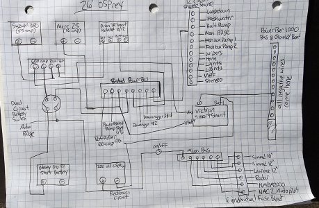
Wanted to tap into the wealth of knowledge here on my complete rewire for my Osprey rebuild. (i'll post recent updates on that thread too) Ripped out a 50 gallon bin of wiring, most went nowhere. Not sure how that's possible but it seemed that way. Gutted everything and starting from ground up. Done a bit of home work and this is the basic wiring scheme I've thought up. Seeing if I could get any tips or advice.
Suzuki 350 (55 amp) and Merc 25 (16amp)
Major Loads: Simrad NAC2 autopilot, Seastar Power Assist/Autopilot pump, 4 downriggers, pot puller, radar, 3 fishfinders, stereo, bait pump, bilge, lights, etc.
Dedicated AGM starting battery. 200+ aH LiFePO4 house battery. Orion TR Smart DC DC charger, SmartShunt Battery Monitor.
Starting circuit....Main Engine positive engine lead to a Blue Seas Dual Circuit On/Off switch and then directly to the starting battery. Negative directly to negative battery terminal.
House circuit.... Kicker positive engine lead to other side of Blue Seas Dual Circuit On/off, then directly to house battery. Negative directly to negative battery terminal.
Ground Buss with leads from negative side of both batteries and to the Orion DC DC. All grounds will go to buss bar.
Positive Wire from + of starting battery to input + on DC DC. Positive wire from + of house battery to output + on DC DC.
The one place I'm not extremely clear on is how to connect my house loads to the house battery. I'm almost thinking about running a 2nd On/Off switch from the house battery to a positive buss bar. From that bus bar, have 1 heavy wire going to a fuse/break block for all my electronics a 2nd heavy wire going to a circuit block for all my downriggers & pot puller, then a 3rd heavy wire going to a fuse/break block for everything else.
My main concern is I really don't want there to be any voltage issues with my fishfinders and radar whenever the downriggers are cycling. Before deciding to go LiFePO4, i was going to run a 3rd battery dedicated to just electronics. However, it seems like a 200 aH house battery should never really have voltage drop issues.
After I typed this, i realized its pretty hard to visualize. I'll try and make a sketch. But any obvious glaring issues anyone sees? Thanks


