Another wiring question...

Baxter

Well-Known Member
I was investigating my boat wiring further, and realized something seemed amiss...

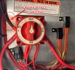
Photo of switch below.

The positive feed from the kicker is tied to battery 1, rather than the "1+2" spot... this seems wrong.


From what I can tell it is still working correctly though. If the switch is turned to any (1/2/1+2) the kicker runs just fine. If the switch is to "off" it does not. So it SEEMS good, but this still seems wrong. To me, what this is doing is having the kicker always pull from battery 1. - but it also surprises me - the connection is essentially always connected to battery 1 this way, but yet still won't start if switch is off. Am I the moron?

Am I crazy? Should that black positive line for the kicker not be connected to "1+2"? That particular wire was done by the dealer, so I always assumed it to be correct. Never second guessed it, but now, as I look into adding a fuse block, and redoing a few things, this has me shaking my head.

Am I dumb, or is this wrong?

My impression on how it should go:
1 = Positive lead from battery 1
2 = Positive lead from battery 2
1/2 = positive lead to everything else.switch.jpg
 
Last edited:
I would remove the switch and see how the wiring is at the backside. Looks like this switch has 3 terminals - top 2 for input 1 and 2 and bottom for outputs.
 

Attachments

  • 5F4A57A4-4DF1-45C7-9669-7C633567F886.png
    5F4A57A4-4DF1-45C7-9669-7C633567F886.png
    544.9 KB · Views: 11
I would remove the switch and see how the wiring is at the backside. Looks like this switch has 3 terminals - top 2 for input 1 and 2 and bottom for outputs.
First, yes, that is the right unit (bluesea 9001e). Also, yes, removing the switch is my next step, I went to remove it - but boat is in the sun right now, went to do that and got baked. :)

I guess thats a good point though, I suppose that even though the wire is coming into the box from that side, it does not necessarily mean it is connected to "1". Perhaps it is still connected to 1+2.... Never even thought of that...
 
bigdogg nailed it - that is exactly what is happening. Blue Sea switches can be confusing in this respect, but the markings on the back is very clear. I would save yourself the trouble. Perko switches are easier to follow, but lower quality in my opinion.

I would be more concerned about the two missing bolts holding your switch to the bulkhead. That switch Is subject to a significant amount of torque, and should secured very well. Blue Sea has had to redesign their switch bodies as some of them were snapping in half. Combination of twisting the knob and forces from those heavy gauge cables take their toll.
So you are suggesting what I mentioned, that it is likely that the one cable for the kicker may actually be connected to 1+2?

As for the bolts, I'll add a couple more, but those two that are holding it are bolted and nutted from behind, the thing is solid as it stands. (but I agree, adding the other two is certainly not a bad idea!)
 
Should go to the common on the switch. Now as for tenafpirt canada regulations, not more than 3 terminals onto a single post
 
Sorry I should have been clearer with my answer. What I meant to say was that with Blue Sea switches can be confusing because the labels printed on the front of the switch do not necessarily align with the actual terminals physically behind those labels. I can see on your switch Position 1 (Left hand side of switch) selects the Deep Cycle battery as the output as indicated by the "DC" written in sharpie next to it (even though I can see the wire from the Deep Cycle battery is actually coming in on the right hand side of the switch). This is what I meant with my earlier comment, that Blue Sea switches can be confusing, but labelling on the backside is crystal clear.

Now addressing your actual question... Yes! i think you're correct. I see exactly what you mean and it was making my brain hurt! BUT, i think this is just an optical illusion... I think that positive lead going to the kicker is physically connected to the terminal that is behind the 1+2 label, the output terminal. It is just run up through the inner left hand side of the switch because it is a more direct path to the kicker, rather than going down and making a big curve back up. Just look at the length of the visible red heat shrink tubing on the main engine (looks like a good 2 inches long) and compare with the visible length of the red heat shrink on the lead going to the kicker, which is about a quarter inch. Good call Baxter.
Ah gotcha. :) All good. I will take a physical look to be sure though.

As for the sharpie labels on the switches, those are old (so I was told) and are to be ignored. The labels on the wires are correct though. I should scratch out the ones on the switch, just never have.


Should go to the common on the switch. Now as for tenafpirt canada regulations, not more than 3 terminals onto a single post

No more than 3. Didn't know that. (Not my doing, bought boat like that). I never questioned it, but I'll fix it up. I assume I can use a bus bar to clean that **** up. (I need to do the same on my negative terminal for the house battery).
 
Not like it's a huge deal. If the boat is insured it should technically pass transport canada regulations based on the survey. However most surveyors don't even know that. Most adjusters fo though lol.

Yeah I will add buss bars for additional posts where need be in electrical installations. I have to follow the rules because of my license and so on so forth
 
The 1, 2 and 1&2 labels on the front have nothing to do with how the inputs and outputs are connected on the back of the switch, they only have to do with what input the switch uses to output power to the switched circuits on the boat. This switch is for a dual battery system.
You are supposed to always select either battery 1 or 2 when running your boat, never use 1&2 as it's only for emergencies where your kids have had the boat up on a sandbar for the afternoon with the music cranked and the one battery is now drained. They then switch to the other battery to start or even both batteries (1&2) if needed. You will also generally always leave a good battery for your unswitched bilge pump - vital if you do not have a self-bailing deck or built-in flotation.
I pulled the switch. The posts on the back match perfectly with labels on the front.
The one cables just enters the box from a different spot but is connected to the correct post
 
I pulled the switch. The posts on the back match perfectly with labels on the front.
The one cables just enters the box from a different spot but is connected to the correct post
The switch itself is just a selector switch, it allows you to choose which battery you want to power up your boat. The back labels do not line up with the front, as there is an output terminal on the back (and also nothing at the off position). The respective inputs line up with the 1 and the 2 on the front, but its the output terminal that lines up with the 1&2. "1/2 = positive lead from everything else" - No, it's the switched positive lead TO everything else, everything on the switched circuits to be exact.
The idea of this switch is to prevent you from ever having both batteries dead at the same time. You should never run your boat with the switch on the 1&2 position because if you accidentally forget to switch off the battery switch and you have also left a console light on, eventually it'll drain both batteries and your bilge pump won't work...
 
I agree with Erik. My labels on the switch do not coincide with the actual terminals on the back. Might want to double check how you’ve wired it. You might have a battery always connected to motors/accessories
 
The switch itself is just a selector switch, it allows you to choose which battery you want to power up your boat. The back labels do not line up with the front, as there is an output terminal on the back (and also nothing at the off position). The respective inputs line up with the 1 and the 2 on the front, but its the output terminal that lines up with the 1&2. "1/2 = positive lead from everything else" - No, it's the switched positive lead TO everything else, everything on the switched circuits to be exact.
The idea of this switch is to prevent you from ever having both batteries dead at the same time. You should never run your boat with the switch on the 1&2 position because if you accidentally forget to switch off the battery switch and you have also left a console light on, eventually it'll drain both batteries and your bilge pump won't work...
Yes, I understand that the 1/2 is a positive lead to everything else. In my original post I said "from", but was not referring to the current direction, but rather that is where that cable was coming from. I do understand though, the direction of the current when the switch is in that position goes from the switch to the device.

If I had simply removed the switch to see where that kicker lead was actually connected I could have avoided this whole thread. That was my only question as it appeared that it was connected to the starting battery (1) terminal (turned out it was not).

In regards to never running in the 1/2 position, this is not entirely true based on what a few people have told me. Perhaps you have a different opinion. This is what I was told by the dealer, an electrician at a separate marine supply store, as well as a few others in various forums etc:

- Start boat with switch in position 1 (starting battery only)
- Switch to 1/2 while running under main power (keeps charge going to both batteries)
- Switch to 2 while trolling or using power while jigging, etc, to isolate battery 1 for starting later

This way, when running out to your spot you keep a charge on both batteries, but when you are draining more than you are charging, use only battery 2 to maintain full charge on starting battery.
 
I agree with Erik. My labels on the switch do not coincide with the actual terminals on the back. Might want to double check how you’ve wired it. You might have a battery always connected to motors/accessories
As noted, the switch itself is wired correctly. The one cable from the kicker that appears to connect to terminal 1, is not actually connected there, just entered the switch box from that position due to cable length. Entering into the switch from that side is what caused all the confusion. After I unmounted it and took a look from behind I could see that everything was as it should be (with the exception of too many connections - something I am going to resolve this weekend).
 
- Start boat with switch in position 1 (starting battery only)
- Switch to 1/2 while running under main power (keeps charge going to both batteries)
- Switch to 2 while trolling or using power while jigging, etc, to isolate battery 1 for starting later

This way, when running out to your spot you keep a charge on both batteries, but when you are draining more than you are charging, use only battery 2 to maintain full charge on starting battery.
That sounds totally fine as long as you have a switch that has “make-before-break” connections… which I am certain you do.

the risk of having a brain fart and accidentally turning it over the “off” position is what scares the crap out of me. If you do that even for a split second while your engine is running, you’re toast.
This is the 9001e. It has "make-before-break" (https://www.bluesea.com/products/9001e/e-Series_Selector_Battery_Switch)

As for switching past "off". While I get that a person could have a dumb moment, I think I should be okay. I have a couple steps I did not include in my process above.

When I get to the fishing grounds, I shut down the main, open up my rear hatch, open up the gas line for the kicker, switch the battery to "2" then proceed to start the kicker, etc. When I am done fishing, I shut down the kicker, open the hatch, close the kicker gas line, switch the battery, fire up the main. I have never and know better than to switch past "off" and never do. I am also the only one who does the switching. Ever. Sure I guess I could screw up one day.

Not sure why I only start the kicker on 2, but I just do. Keeps 1 at max all the time. (both batteries are the same, so doesn't really matter, as long as I always have juice for the main). (Batteries are both group 24, 800 CCA, 150 Min, 80 Amp Hours)

All that said, I have thought about getting an ACR, perhaps I will some day, but not doing it at the moment.
 
Last edited:
Baxter, when I look at your original post, something is wrong.
You have the starter battery positive connected to input 1, as well as the kicker starter positive. You are correct, the kicker is then always connected to battery 1, and not thru the switch.
I also don't understand why it would not start if the battery switch is turned to "Off" because it doesn't go thru the switch. I'll be watching this thread to see what washes out.
It does go through the switch. The kicker is hooked to the output post, not the battery one post.
It looks like it goes to battery 1 but when you pull the switch and look behind it is clear that it does not. Wire is just run that way so it could reach.
 
Last edited:
Back
Top