2 stroke firing in reverse order

Bordeau

Active Member
I have completed a rebuilt of a 60hp Envinrude 1988 model # E60ELCCR and I am puzzled. The engine starts but backfires and runs only on cylinder 2. When I disconnect spark plug #1 and 3, no change in RPM or the way it runs.

The timing light shows cylinder #2 firing at the correct time. I am confused as to why #1 and #3 spark plugs ignite in reverse order. I marked all 3 cylinders’ TDC. When the timing light is plugged on cylinder #1, it shows my TDC mark for cylinder #3. When I move the timing light to cylinder #3, it shows that cylinder #1 is firing just before #1’s TDC mark.

I labelled all wires before taking them off and now I am thinking I might not have been so diligent after all. Is it possible that I crossed 2 wires? If so which ones?
 
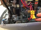
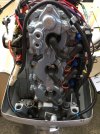
Are those the plug in style coils? Or the pigtail style into a plug ?
 
Sorry I don't understand your question. Can you tell from these pictures?
 

Attachments

  • IMG_2801.JPG
    IMG_2801.JPG
    280.8 KB · Views: 68
  • IMG_2802.JPG
    IMG_2802.JPG
    230.2 KB · Views: 67
Those are the plug in style. Which means they have small plugs for the input on the coils. the small blue plugs on the coils. they are blue because that is a CDI ignition pack. Its been replaced before.

Unplug number one and 3 and swap the coil input plugs. try it. See what happens
 
Sweet. I am learning something new.
I did not label the plug leads as they all look the same.
I will try switching them when I have time this week and I let you know.
 
Always take pictures with your phone as to where wires land...even using colour coded tape around each and then a picture showing which terminal they connect to. Phones are handy and quick for this.
 
hose are the plug in style. Which means they have small plugs for the input on the coils. the small blue plugs on the coils. they are blue because that is a CDI ignition pack. Its been replaced before.

Unplug number one and 3 and swap the coil input plugs. try it. See what happens
Always take pictures with your phone as to where wires land...even using colour coded tape around each and then a picture showing which terminal they connect to. Phones are handy and quick for this.
IMO GREAT advice is rare on this forum; thanks for proving me wrong
 
It worked! Thanks SH.
The short wire from cyclinder 1 barely made it to the plug on #3. The engine runs smoothly and all 3 cylinders are firing on time.
The service manual I have does not describe the timing specs for idle or WOT. Online I found
idle at 750 RPM should be 1 degree BTDC
WOT at 5000 RPM at 28 Advance

Please confirm or correct.


I would have to look in the book for WOT timing spec. Which is the only thing that matters.

How I used to do it, was mark where the timing wheel or trigger assembly would open to at WOT. Somehow.. and have to do it precisely. Somehow.. Then engine running at idle speed with the timing light dialed and the timing indicator set at TDC. ( that's another procedure ) . Grab the timing base and move it by hand all the way up, and read the timing light against the flywheel to get the proper timing. Engine doesnot have to be getting wide open rpm to adjust wide open timing. Hope that makes sense. Only way I've ever done it. It's the skip the dishes way and works everytime. Cheers
 
Last edited:
I followed this procedure to set up the idle speed.
It was running well at home with a garden hose and earmuffs. Once in the water at the boat ramp, it could not idle. Is it normal that there is such a different between hose flush and submerge in water? Or is it my adjustments that are not to spec?
 
Are those the fixed carburetors or do they have idle screws?

Boat must be on water or a test tank to set the idle speed. The back pressure in the exhaust when its submerged in water and with a load makes it quite a bit different. Idleing in gear in the water is the way to set the idle speed. I always just tie the boat to the dock.
 
Last edited:
There are fixed carbs. Ok I will be back in the water Saturday.

I purchased a book that covers several models but it does not give any specific adjustment lenght. Do you happen to have the service manual that will tell me the lenght for the throtle cam and the timer adjustment screw? That would give me a good reference to start with.
 
Im sure i do, however I don't think the book is much to reference. A lot of this stuff what your doing is by feel. I don't know how the mechanical portion of that engine is as compared to a perfectly machined block, piston, and rod assembly.

All the carb throttle plates should be adjusted closed. Then you can play with the idle timing screw and throttle cam etc. Should run in gear about 700 to 750 rpm. idle in neutral will be a little higher. Out of the water most of the time they turn at about 900 rpm. Don't try and make it run past that you could damage the gear and clutch dog.
 
It worked for 20 minutes until the head blocks started leaking.

During the rebuild, I had to machine both head blocks in order to eliminate some warps. Now they are perfectly straight. The problem is that I can't torque the screws to spec as they squeeze and stop the cam from turning. I did put some RTV gasket maker and torque to the max while allowing the cam to turn, but I guess the gap is too big and the plates need to be tighter.

Is there a way to make a better gasket or is it the end for this engine?
 
Last edited:
I have no idea how far you machined the cylinder head. Your saying the bolt shoulder hits before the head gets tight? Eeek. You will have to make the bolts shorter. No way to make a head gasket larger. The mechanical portion of any engine needs to be absolutely a well put together rotating machine and everything needs to go together easily or something is not right.
 
There was lots of corrosion and in order to clean the surfaces properly, I machined the heads too far. If I tighten the screws, the heads squeeze the cam and stops it from turning. That's why the screws are not to specs.
I put some gasket maker thinking it will seal the tinny gap between the heads but it got pushed out. Now there is a visible leak between the heads.
Any suggestions?


Get another head. Dont machine it. Fresh head gasket and use evinrude gasket maker. The brown stuff. Done deal . I probly have one
 
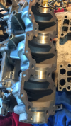
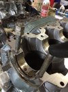
There is no gasket. It is the assembly of the cylinder block to the crankcase cover with only a sealant in between. These are the 2 pieces which envelop the crank shaft. I took these pictures as I was taking the engine appart.


IMG_3250.PNGIMG_2834.JPG
I don’t think it is worth putting more time and money into this old engine. I learn a lot by rebuilding it and it almost worked. Now it is only good for parts. Do you need any?
 
Back
Top