Suggestions, short and quick. use Grade 5052 aluminum plate and any extrusions (angle, flat bar, etc) use t-6061 t6. It probably wont be found at the neighborhood ace hardware store. These grades have excellent corrosion resistance and if I'm not mistaken the stress strength on 5052 is around 55,000 pounds. that's 55 thousand. I used er 4043 tig rods and 4043 mig wire for the inside welds. I only tigged where it had to look pretty.
I used 1/2 inch plate cut out with relief holes for lightening for the transom plate with 1/4" internal stiffeners in two equidistant places inside. (be sure to provide drainage between the internals you you dont have to mop out water. and 1/4" plate for the bottom piece with 1/8 sides and top. The engine plate was of 1/2" and doubled at the top where it projected above the top of the bracket with 1/4" gussets to kinda help out from springing. I put a screw in drain plug in the bottom to check it once in a while and a zinc plate on it too. No paint under the zinc. All this you may already know so please dont be offended if I tell you. I put Beckson plates over each compartment to access the internal bolting. I otherwise wouldn't have put any kind of penetration in the top. Access plates leak unless you get high dollar ones. I dont like 'em.
I used 309 S/S bolts through bracket and transom with fender washers and nylock nuts in addition to lock washers. Kinda like wearing a belt AND suspenders but I want it all to stay put and lock washers are cheap. The only thing I goofed on was that I tried to spin the nut on the first one with an impact. S/S doesnt take too kindly to fast bolt ups so I galled one. Had to cut it loose and do it again. Be generous with 3m 5200. Seal EVERYTHING but just a thin bead around the perimeter of the bracket to transom fit. If you ever have to take it off, you'll appreciate this advice.
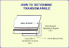
Transom Angle (Degrees)
Measuring The Transom Angle (Degrees):
Using a standard carpenter's square ruler, slide the long side of the ruler (24") under the boat at the keel point. Slide forward until the short side of the rule (16") touches the transom straight up. Measuure the distance from the keel point to the inside corner of carpenter’s square ruler (see sketch). Each 1/4" is equal to 1° degree. Example: 3” equal to 12? degrees.
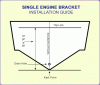
Single Engine Layout
Single Engine Bracket Installation
You need to determine the vertical (centerline) of your transom.
From the bottom horizontal line and go up:
For a 20" shaft engine - go up 19"
For a 25" shaft engine - go up 24"
For a 30" shaft engine - go up 29"
Then measure up the centerline (vertical) from the keel point 19, 24 or 29 inches.
At the 19, 24 or 29 inches mark a top line.
The top line is where the top of the engine bracket bolts up against the transom.
(Not the side were the engine goes.)
Check to make sure there is enough clearance inside the boat when the
Bolts* and nuts are installed.
*Bolts, nuts and washers must be stainless steel to avoid rust.
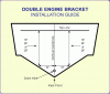
Double Engine Bracket
Double Engine Bracket Installation
You need to determine the centerline (vertical) of your transom. Mark a line from top to bottom for a centerline.
Then from the keel point on the centerline (vertical) measure up until you get 13" of transom on both sides of your centerline. Mark a line across horizontally there.
From the bottom horizontal line and go up:
For a 20" shaft engine - go up 19"
For a 25" shaft engine - go up 24"
For a 30" shaft engine - go up 29"
Then measure up the centerline (vertical) from the keel point 19, 24 or 29 inches.
At the 19, 24 or 29 inches mark a top line.
The top line is where the top of the engine bracket bolts up against the transom.
(Not the side were the engine goes.)
Check to make sure there is enough clearance inside the boat when the
Bolts* and nuts are installed.
*Bolts, nuts and washers must be stainless steel to avoid rust.
Up 1” for every 12” of set back


")