gungadin
Well-Known Member
Last year I installed a “tiny tach” on a 50hp tiller operated 2015 Yamaha outboard. Because it was an inductive tachometer it was a simple install. I have found though that although it is accurate at higher rpm is jumps around a lot at idle and anything below about 2000 rpm.
This year I am going to install an analog tachometer ( Faria model 33104). I am a little confused about where to pick up the "signal" and "ignition on" wire under the cowling of the outboard. I have run 16ga wires from the tachometer to under the cowling for both the “signal” and “ignition on” wires, but this is where my confusion arises.
The instructions that came with the tachometer say to hook up the signal wire to the unrectified side of the alternator, but also say there may be a tach hook up wire in the control box. Of course I have no control box.
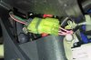
A search on the internet yielded the possibility of several different coloured coded wires as a tach hookup wire. I have found a green with red stripe (Tachometer??) and yellow (key on ??) along with a pink and grey wire for a total of 4 (20 ga. ) wires at a small connector that goes into the tiller handle.
I think these care the wires I need to splice into, but was hoping some one on here has first hand knowledge about an aftermarket hookup.
It also appears that I can purchase a connector that would allow me to hook up to a OEM tachometer, but I don't have one of those, and as all that is required is a signal and key on and ground wire, so I should be able to hook it up. Any help here would be appreciated.
This year I am going to install an analog tachometer ( Faria model 33104). I am a little confused about where to pick up the "signal" and "ignition on" wire under the cowling of the outboard. I have run 16ga wires from the tachometer to under the cowling for both the “signal” and “ignition on” wires, but this is where my confusion arises.
The instructions that came with the tachometer say to hook up the signal wire to the unrectified side of the alternator, but also say there may be a tach hook up wire in the control box. Of course I have no control box.
A search on the internet yielded the possibility of several different coloured coded wires as a tach hookup wire. I have found a green with red stripe (Tachometer??) and yellow (key on ??) along with a pink and grey wire for a total of 4 (20 ga. ) wires at a small connector that goes into the tiller handle.
I think these care the wires I need to splice into, but was hoping some one on here has first hand knowledge about an aftermarket hookup.
It also appears that I can purchase a connector that would allow me to hook up to a OEM tachometer, but I don't have one of those, and as all that is required is a signal and key on and ground wire, so I should be able to hook it up. Any help here would be appreciated.